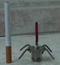
The omni antenna, with a cigarette for scale.
| This is wireless.gumph.org's cached copy of http://flakey.info/antenna/omni/quarter/ The original page may have changed since we took this copy. Click on this link to go to the original page. |
The omni antenna, with a cigarette for scale.
This omni directional antenna was built in response to finding a simple diagram in an old book. After scaling to the correct frequency, it was built to help augment an 802.11b vehicle-based community wireless network effectively and cheaply.
The omni-directional antenna was built using an N-type chassis mount connector with short lengths of stiff fencing wire soldered into each corner hole. The driven element (the wire soldered into the centre, or conductor) was a quarter wavelength (32 millimetres) as was each ground plane (four soldered around the body of the connector). Each groundplane was cut to length and then bent over at 30 degrees from the horizontal to attempt to match the impedance to 50 Ohms.

A semi-technical drawing of the antenna (click to enlarge).
I have been emailed by people using this design with a bend of 45 degrees, and that this worked better to give 50 Ohms. The original prototype (with 30 degree bends) is still working well after a year and a half. Although looking back at the photos, the prototypes may well have been more like 45 degrees, both seem to work well. In fact I have mended these in the field by eye, after sustaining vehicle damage, and still they worked well.
The N-type connector was obtained from R.S. at Ł2.93 (part number 112-2139). On the packaging it had printed: Telegartner (presumably manufacturer) Type: N-Flanschbuchse J01021H1082 Tel +49 (0) 7157/125-0 Fax -120
Prototypes were made with thinner wire (twin and earth from domestic main installations), but they were too flimsy to store or use reliably. We ended up using the thickest, stiffest fencing wire that would fit in the holes of the N connector body. It was only bendable with two decent sets of pliers which means that in use it remains in place, even with quite a heavy bird on it...
Soldering to the "solder bucket" in the centre of the connector was easy because it has been pre-tinned. The same was not true for soldering to the holes in the body of the connector. The area around these needed a good roughing up with sandpaper, then tinning by applying solder until it flowed, then the wire soldering into the holes until all the solder flowed together, while the whole connector is hot. This means the connector gets really sodding hot (ensure it's in a safe place and well held - a vice, mole-grips), fortunately the dialectric (insulating plastic) did not melt, as has happened on cheaper connectors. All solder connections were tested by "wiggling" when cool - a very telling test.
I have had many emails from people who have made this design and have had good results, some of them looking much better than the original prototype above. Since making the first one I have bought an 80 Watt soldering iron (though not temperature controlled) and this has made the soldering much easier, so I would recommend using nothing less than 80 Watts.
 | This picture was sent to me (click to enlarge). Antenna made by John, thanks for the photo. This one is made using brass rods bought from a local hobby shop, heatshrink tubing and some neat soldering! (he used 135 Watt iron) |
The central conductor was shrouded with the outer plastic stripped from wire of the same gauge. Initially this was not even pushed all the way down to the dialectric (the gap shows in the photo at the top of the document).
Since then heatshrink tubing has become hot favourite for insulating, it is more effective and easier to fit, and should insulate right down to the dialectric. Be careful to cut it square and clean so that it does not split when heated, as splits can travel over time.
So far this antenna has not seemed to need more weatherproofing.
For temporary mounting outdoors sealing the joint between the N connectors with self-amalgamating PTFE (Polytetrafluoroethylene) tape, silicon sealant , heatshrink etc. helps to avoid ingress of moisture into the cable.
For long term installation outdoors it would be prudent to house the antenna and N connection in a plastic food container (check that it is safe for use in a microwave oven first, and be aware that some plastics effect signal strength).
When we have used this antenna it has been sufficient to screw it to the cable and affix the cable securely; this is using URM67 coaxial cable which is 10mm outer diameter and resists bending . The antenna is so strong and light the cable seems to provide adequate mounting in itself.
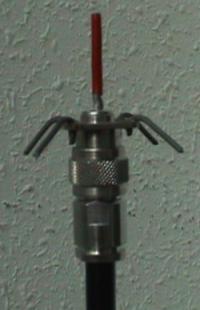
The antenna mounted on an N-type cable.
What can I say? A bargain at Ł2.93, assuming you find the fencing wire in the rubbish (or a local fence) and don't really have to pay for your solder.
From experience of useage in a variety of situations and surroundings, I would estimate the gain of this antenna to be around a 3 to 5dB improvement over a Buffalo pcmcia card internal antenna , with a much smoother polar coverage (allowing for the losses in a pigtail, and 6 or 7 metres of URM67 cable, and connectors).
In use on a flat field, using two of these antennae attached to pcmcia 802.11b cards via cable and pigtails, we were able to maintain an 11Mb/s network at between 400 to 500 metres with clear line of sight.
You may be able to tell from the lack of absolute measurments in my results that I do not have access to calibrated test equipment, or the time to carry out well documented tests. If anybody does, please let me know the results!
Apart from the fact it works really well, no-one has yet popped on their lab-coat and done any high-brow tests on this "homebrew twig", and of course manufacturers recommend you don't do anything which they don't recommend, or attach non-proprietary stuff to their stuff. Of course.
The cigarette shown in the picture is for scale only. Do not try and smoke it.
Author: spacepleb@psand.net
Copyright (c) 2002 Psand Limited. Permission is granted to copy, distributed and/or modify this document under the terms of the GNU Free Documentation License, Version 1.1 or any later version published by the Free Software Foundation; with no Invariant Sections, with no Front-Cover Texts, and with no Back-Cover Texts. A copy of the license is included in the section entitled "GNU Free Documentation License".